Cam Linkage Mechanisms
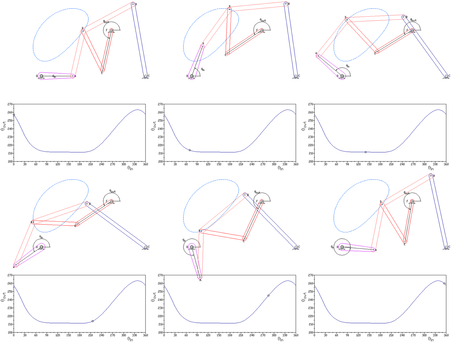
22 designed a new robot structure, where a seven-bar crank-slider mechanism was combined with a cam to generate a precise target path.
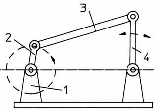
Cam linkage mechanisms. The novel lower-limb rehabilitation system is composed of a body weight support system to unload the body weight, and two cam-linkage mechanisms to generate the natural gait trajectory and guide the patient's feet. Cam mechanisms take in rotary (circular) motion and puts out another form of motion. The simplest closed-loop linkage is the four-bar.
Hence it can be explained easily that Cam is a mechanical component that transmits reciprocating, oscillating or linear motion to Follower. I used cardboard with other craft materials. Cam is a mechanical component which is a rotating circle or eclipse about the minor axis of the Follower.
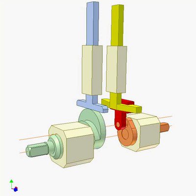
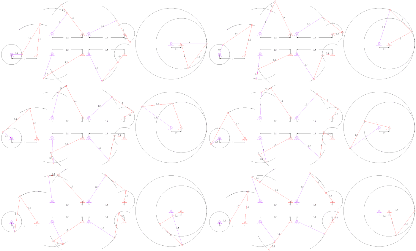
Cams convert ordinary shaft rotation into a more complicated pattern of motion. For specific information on linkages please refer. Eccentricity of the green circular cam = length of the orange crank Radius of cam pitch circle = length of the red conrod.
Sturdy, double-pivoted stop ensures precise switching. The DX-90 Monster Mech, over-center cam mechanism BETTER protects against side-bolt punching. The bars move in opposite directions.
CAM MECHANISMS Cam makes a higher kinematic pair with follower. A thorough research as well as a project was done by me before finally writing down this article. Cam and follower are a higher pair.
Rigid bodies and kinematic constraints are the basic components of mechanisms. A cam, a follower and a frame. Valve mechanism for operating the valve in engine block (straight poppet valve).
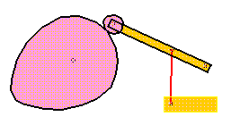
A constrained rigid body system can be a kinematic chain, a mechanism, a structure, or none of these. Linkage are composed of links and lower pairs. As the roller surface goes along the edge of this three-lobed cam from peak to valley, there is a quick change of direction in the follower arm, which may also create a noise.
Mechanisms generally consist of moving components that can include:. Eccentricity of the green circular cam = length of the orange crank Radius of cam pitch circle = length of the red conrod. MechDesigner models machines, mechanisms, cams gears, belts.
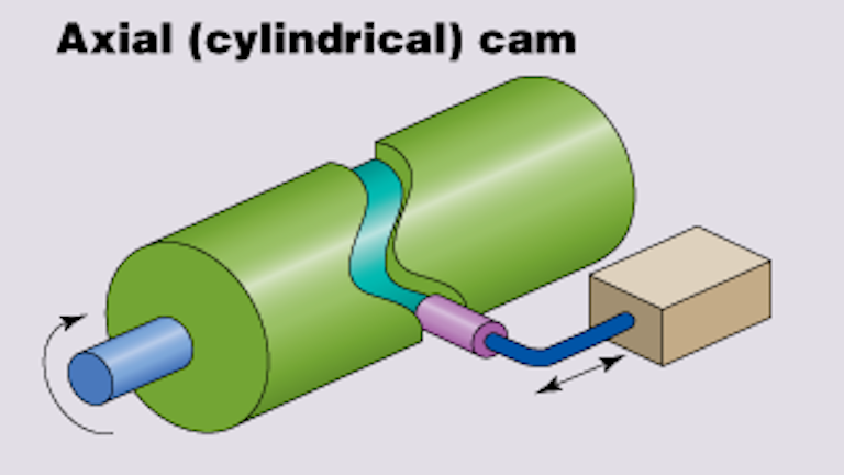
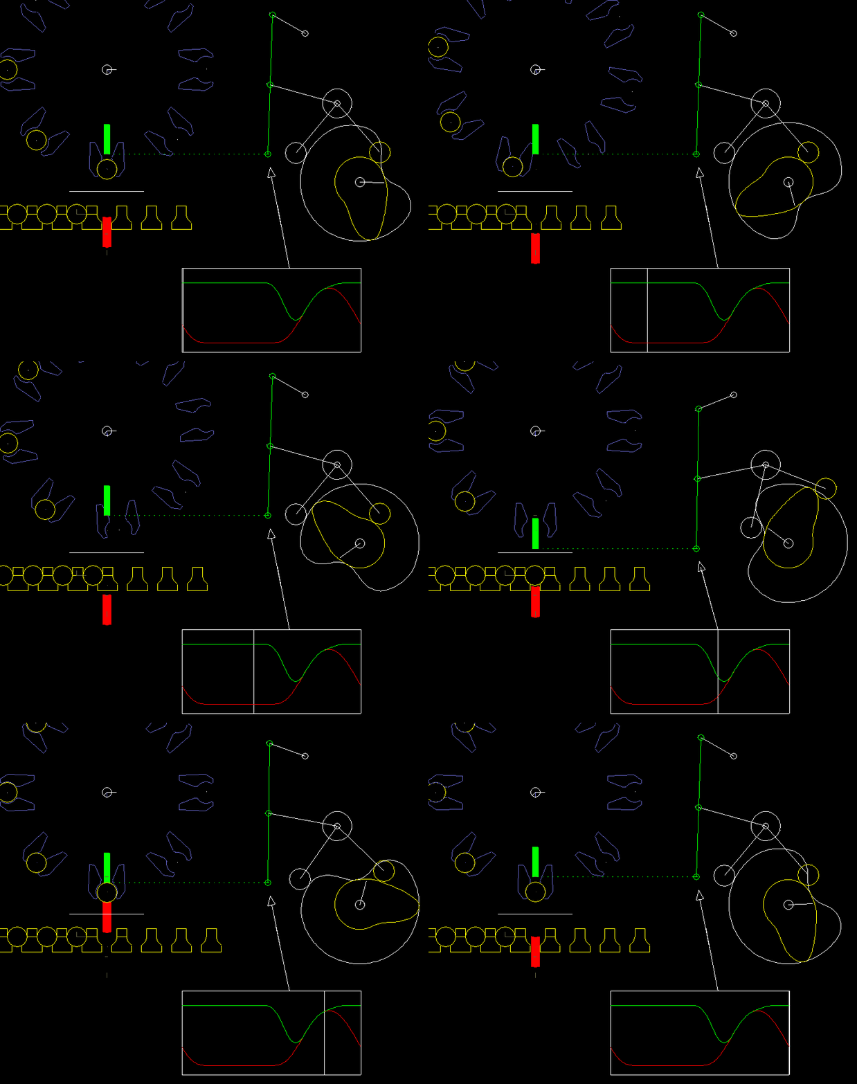
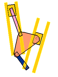
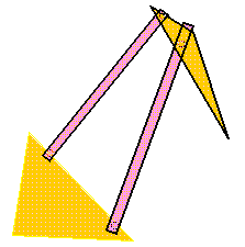
KINEMATICS OF LINKAGE MECHANISMS. The blue follower and the yellow rocker have the same motion. A cam is a rotating or sliding piece in a mechanical linkage used especially in transforming rotary motion into linear motion.
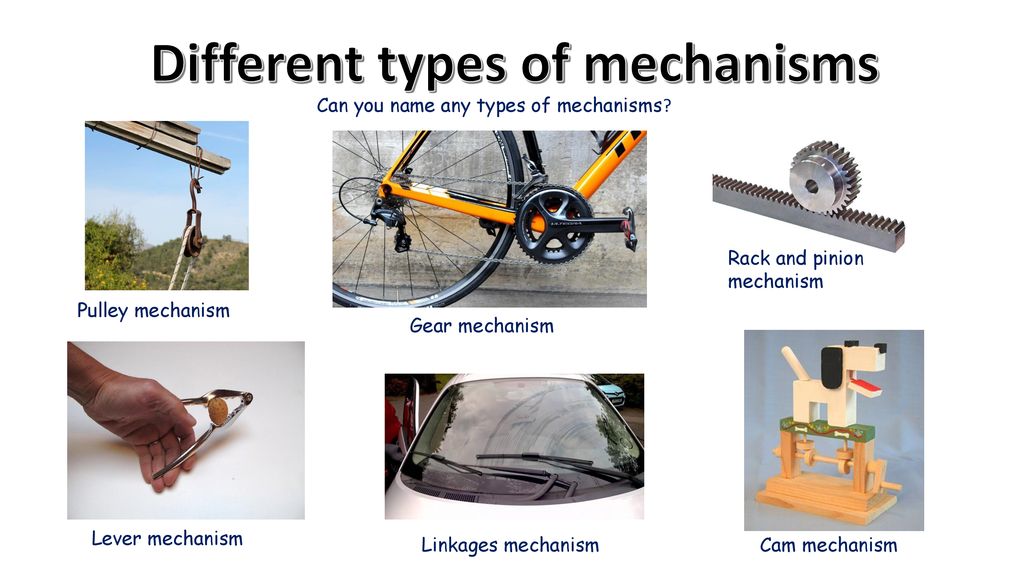
A cam mechanism is one of several mechanisms that can generate a linear motion. There are clearly an infinite number of mechanisms available but the notes and links are concentrating on the specific ones as listed below. Effective cam design method which is based on motion design of the cam pitch curve by “blends” of the traditional profiles, formed by superimposing three functions;.
Home Engines Gears Indexing Pumps Linkages Couplings Pneumatics Electronics Electricity Arduino Reciprocations Straight Line Cams Thermodynamics Power Generation Miscellaneous Feedback FAQ About. Introduction to Mechanisms 1. Mechanism Design Software :.
The mechanism must be capable of operating in both balanced and unbalanced states. 3.1.1 Cam Driven Linkages. The outline of the paper is as follows.
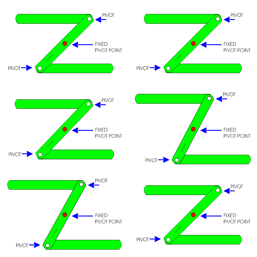
All components of the mechanism must be exhibit a safety factor of 5 in regards to static failure. It is often a part of a rotating wheel or shaft that strikes a lever at one or more points on its circular path. Another way of describing this linkage is the direction of movement in one rod is reversed in the other rod.
Types of Engine Valve Mechanisms. Cam’s shape is usually an oval or an imperfect circle or an eclipse. Build a simple linear mechanical movement and adapt it into your own kinetic craft.
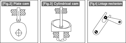
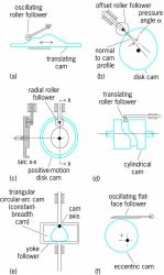
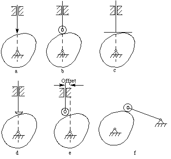
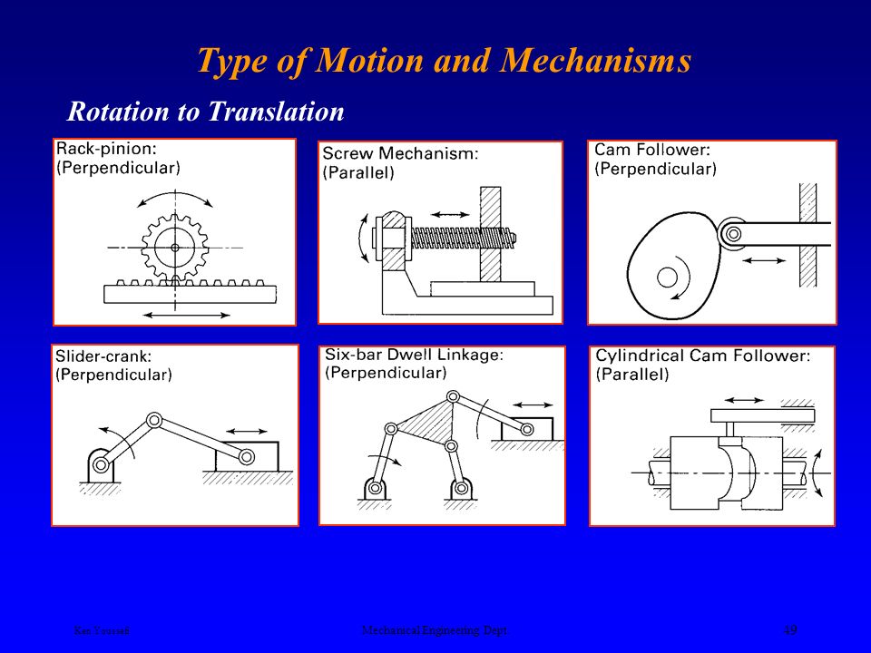
Types of Mechanisms. The transformation of one of the simple motions, such as rotation, into any other motions is often conveniently accomplished by means of a cam mechanism A cam mechanism usually consists of two moving elements, the cam and the follower, mounted on a fixed frame. For example, if the output link must.
A mechanical linkage whose purpose is to produce, by means of a contoured cam surface, a prescribed motion of the output link of the linkage, called the follower. Gears and gear trains Belt and chain drives Cam and followers Linkage Friction devices, such as brakes and clutches Structural components such as a frame, fasteners, bearings, springs, lubricants Various machine elements, such as splines, pins, and keys. Mar 17, 17 - Explore cary foster's board "Rotational to linear mechanisms" on Pinterest.
A Practical Example - Eccentric Cam:. By doing this the mechanism’s core components are shared, minimizing the potential for manufacturing or assembly variation between the two modes of operation. Cam devices are versatile, and almost any arbitrarily-specified motion can be obtained.
Each design may include many different complex motions. The moving members are the cam (2) and the follower (3) (see an example of a cam mechanism in Figure 1). Displacement, velocity and acceleration analysis in simple mechanisms:.
And a cam disk opens it forcibly. More Cam Questions :. See more ideas about Mechanical engineering, Mechanical design, Mechanic.
• Mechanisms are assemblage of rigid members (links) connected together by joints (also referred to as Mechanical linkage or linkage). Important Concepts in Velocity Analysis. The influence of kinematic constraints in the motion of rigid bodies has two intrinsic aspects, which are the geometrical and physical aspects.
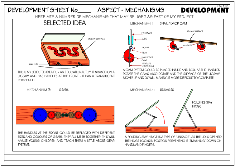
Linkages, while useful, cannot achieve all possible motions. In A Cam Mechanism, The Viewer Makes The Following Movements:. The Snail / Drop Cam:.
As the camshaft turns, the cam operates the valve. Example cams and questions:. If this is done the method of determining the velocity and acceleration which has been described in "Theory of machines, Velocity and acceleration.
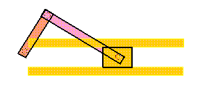
You can easily model this type of mechanism with the Cam-Follower feature in the COMSOL® software. A crank and slider is a common, simple mechanism used to convert rotational motion into reciprocating linear motion, or motion that goes back and forth along a straight line. This article provides you a good knowledge of Cam and Followers.
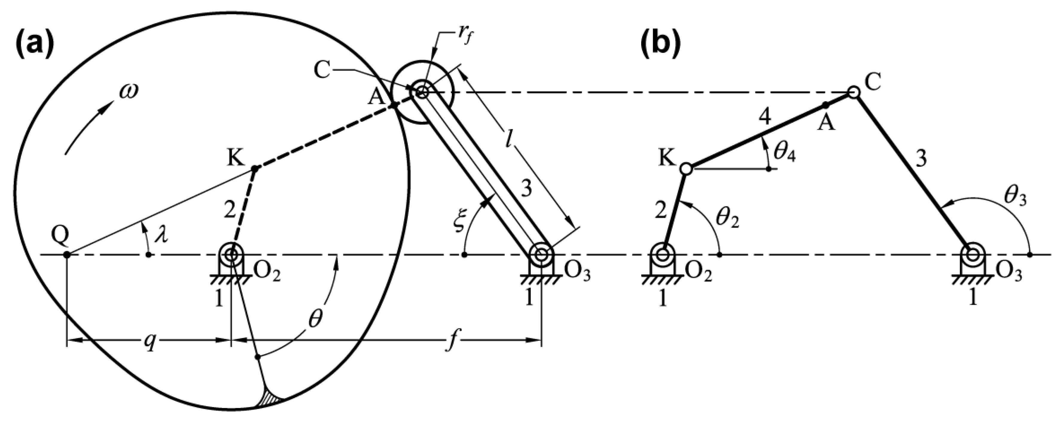
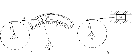
In engineering, a mechanism is a device that transforms input forces and movement into a desired set of output forces and movement. The Equivalent Mechanism For A Cam And Follower In many cases an equivalent mechanism using lower pairs can be substituted for a given cam and follower, possibly only over a limited range of stroke. The cam can be a simple tooth, as is used to deliver pulses of power to a steam hammer, for example, or an eccentric disc or other shape that produces a smooth reciprocating motion in the follower, which is a lever making contact with the cam.
A site dedicated to animation of mechanisms, pneumatic, hydraulic and electronic components Animated Mechanisms. A mechanism considered to be an assembly of mechanical items designed to achieve a specific purpose within a machine. Simple Example and Detailed Profiles:.
It is the mechanical portion of amachine that has the function of transferring motion and forces from a power source to an output. Just like a four bar linkage, cams are great at creating unique motions. A means of measuring and recording the kinematic and dynamic characteristics of the slider-crank mechanism’s motion must be incorporated into the design.
There are many kinds. The German scientist Reuleaux provides the de. The most common types of linkage are shown below.
The direct-drive cam mechanism (entry level safes) is a smooth direct-drive connection from the mechanism to the door bolts.It's simple, yet very effective in locking the safe. A complete know-how of the widely used mechanism. Cams - Definition, Profiles and Followers:.
Cam - attached to a crankshaft, which rotates Follower - touches the cam and. There are six links in Klann mechanism they are fixed frame, crank, upper rocker arm, lower rocker arm, and connecting arm main leg link. The cam mechanism is a high auxiliary mechanism composed of three basic members:.
Model anything from a simple spray actuator. Slider-crank mechanism, arrangement of mechanical parts designed to convert straight-line motion to rotary motion, as in a reciprocating piston engine, or to convert rotary motion to straight-line motion, as in a reciprocating piston pump. The absolute velocity of any point on a mechanism is the velocity of that point with reference to ground.
This content and associated text is in no way sponsored by or affiliated with any company, organization, or real-world good that it may purport to portray. PDF FILE - POSTER - CAM MECHANISMS :. A general cam mechanism is typically referred to as a three-link mechanism with a single degree of freedom, which consists of two moving members mounted on a fixed frame (1).
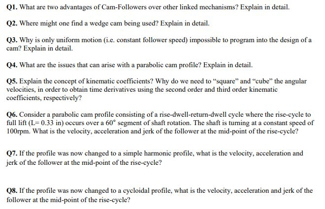
Three cam disks per switching stage prevents unilateral lifting forces. I) 40mm Rise With Parabolic Movement For 1 Degree Cam Rotation Angle (0 < 𝜃 < 1/2 For 𝑠 = 2𝜃^2 , 1/2 < 𝜃 < 1 For 𝑠 = 1 − 2(1 − 𝜃) ^2), Ii) Standby For 1 Degree Cam Rotation Angle, Iii) 40 Mm Descent With Third Degree Curve # 2 For 1 Degree Cam Rotation Angle (s=. The camshaft gets motion from the crankshaft.
Cam mechanisms are widely used because with them, different types of motion can be possible. Linear Motion by Cam Mechanism:. This paper presents a new approach to eliminate the residual vibration of shedding system and the associated mechanism that connects the heddle shafts with the cam mechanisms.
Gallery of application showing mechanisms, gears, motions, cams. In Section 2, the conceptual design of the cam-linkage mechanism is briefly described. The cam modulated linkage, also known as the cam-integrated linkage or the combined cam-linkage mechanism, is a composite mechanism consisting of at least one cam-follower pair in combination with.
A mechanism is the heart of a machine. Devices that utilize cams to transform one type of motion into another are typically composed of three main parts:. Cams are comprised of a cam shaft, typically an irregularly shaped cylinder, and a follower, that is pushed by the cam shaft to create reciprocal motion.
The cam is a member with a curved profile or groove, generally an active member for constant-speed rotary motion or reciprocating linear motion. Students design and create cam toy machines with moving objects/characters that sy…. A cam timer is s.
A cam is the typical mechanical component used in the rotary-linear motion conversion mechanism. BENEFITS of Liberty's LOCKING MECHANISMS. According to the location of the valves, the valve mechanism is of two types:.
The CAD files and renderings posted to this website are created, uploaded and managed by third-party community members. Cams are the excellent choice because of the following characteristics:. The basic nature of the mechanism and the relative motion of the parts can best be described with the aid of the accompanying figure, in which the moving.
The over-center cam removes all pressure from locking bolt with a unique "dead lock. The mechanism used to implement this behavior, known as a cam-follower mechanism, plays an important role in many applications, including internal combustion engines, printing control mechanisms, textile weaving machines, and valves. Motion Control Using.
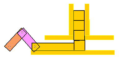
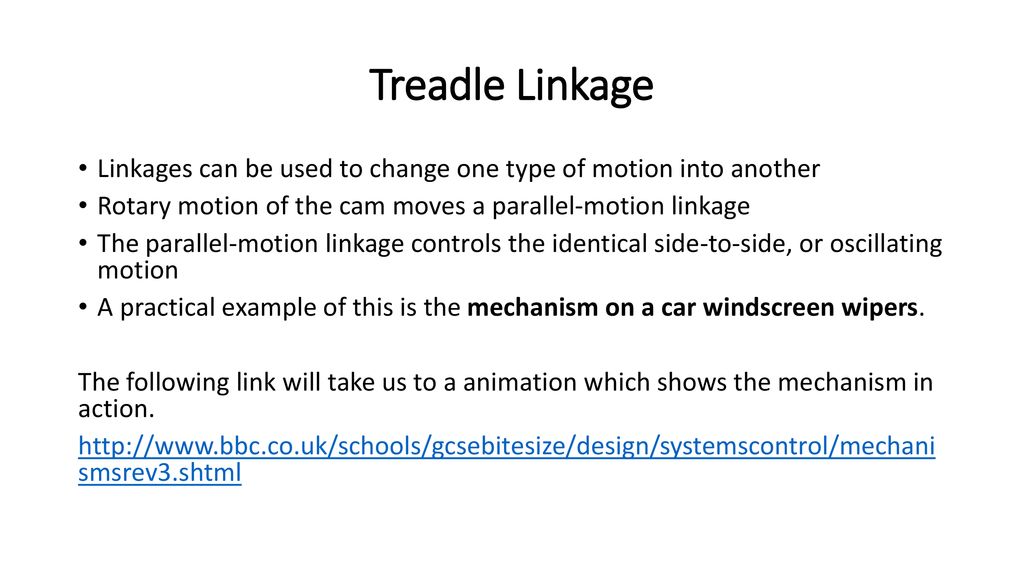
A cycloid, a ramped versine, and a ramp called as. The cam itself is the small mechanical part that looks like a guitar pick or a tear drop. This is an example of a combination of cam and linkages.
This is accomplished by keeping one or more followers in contact with the surface of a rotating cam. Familiar examples are the piston and crankshaft on a locomotive or in a car engine. As the top rod moves to the left the bottom rod moves to the right.
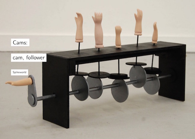
Synthesized the cam-linkage mechanisms with one or more cams for precise path generation, while Soong proposed a novel cam-geared mechanism for path generation. A simple, working model can be built out of household materials, wood, or metal. GRADES 6 - 8, Social Studies, Science, EngineeringLesson Overview Cam toys (aka automata) use hand-powered mechanisms to create cyclical motions that animate a scene.
Switching stages, latching mechanisms and cover plates are bolted together to form the basic switch. The blue follower and the yellow r. They are made of two main parts:.
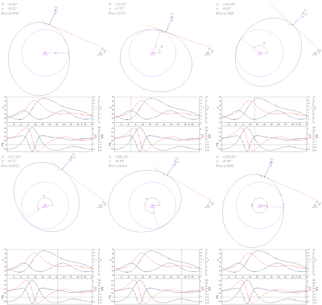
See more ideas about Mechanical design, Hinges, Mechanical engineering. Cams can provide unusual and irregular motions that may be impossible with the other types of mechanisms. Cams and linkages The cam below would trigger a movement of three valleys and peaks per rotation.
In addition to tightening things with ease, cams are also used to change rotary motion into reciprocal motion. Linkages) for both cam and servomotor application. It provides all of the kinematic and force data you need to make the right design decision.
Proudly powered by Weebly. The cam, the shaft (or rotating wheel), and the lever (also called a cam follower). Klann mechanism is a planar mechanism converts the rotary motion of the crank to linear movement of the foot for one-half rotation of the crank.
Click Here for Videos of. The valves are operated by cams mounted on a camshaft.

Schematic Representation Of A Generic Disc Cam Mechanism With Offset Download Scientific Diagram

Pin On Napady

Q Tbn 3aand9gcq 26twritmdlyscv3t0vu0c4hwdbhkvnecag Usqp Cau
Cam Linkage Mechanisms のギャラリー

Conceptual Design And Dimensional Synthesis Of Cam Linkage Mechanisms For Gait Rehabilitation Sciencedirect

Equivalency Of Circular Cam And Linkage Mechanisms 3 Youtube
Low Cost Automation Tutorial January 10 Archives

Pin On Mechanisms

Example Power Calculation For Cam Mechanism

The General Kinematic Pair Of A Cam Mechanism Intechopen

Mechanisms Index Page
Q Tbn 3aand9gcrjo45tvo6qcalduvewwsanzrad9 Qcocyo2rk1phrlyqpel7bj Usqp Cau
Examples Of Mechanisms

Pdf Analysis Of Novel Geared Linkage Mechanisms

Optimal Dimensional Parameters Of The Cam Linkage Mechanisms For Download Table
Design Of Automata 14 Steps With Pictures Instructables
Examples Of Mechanisms
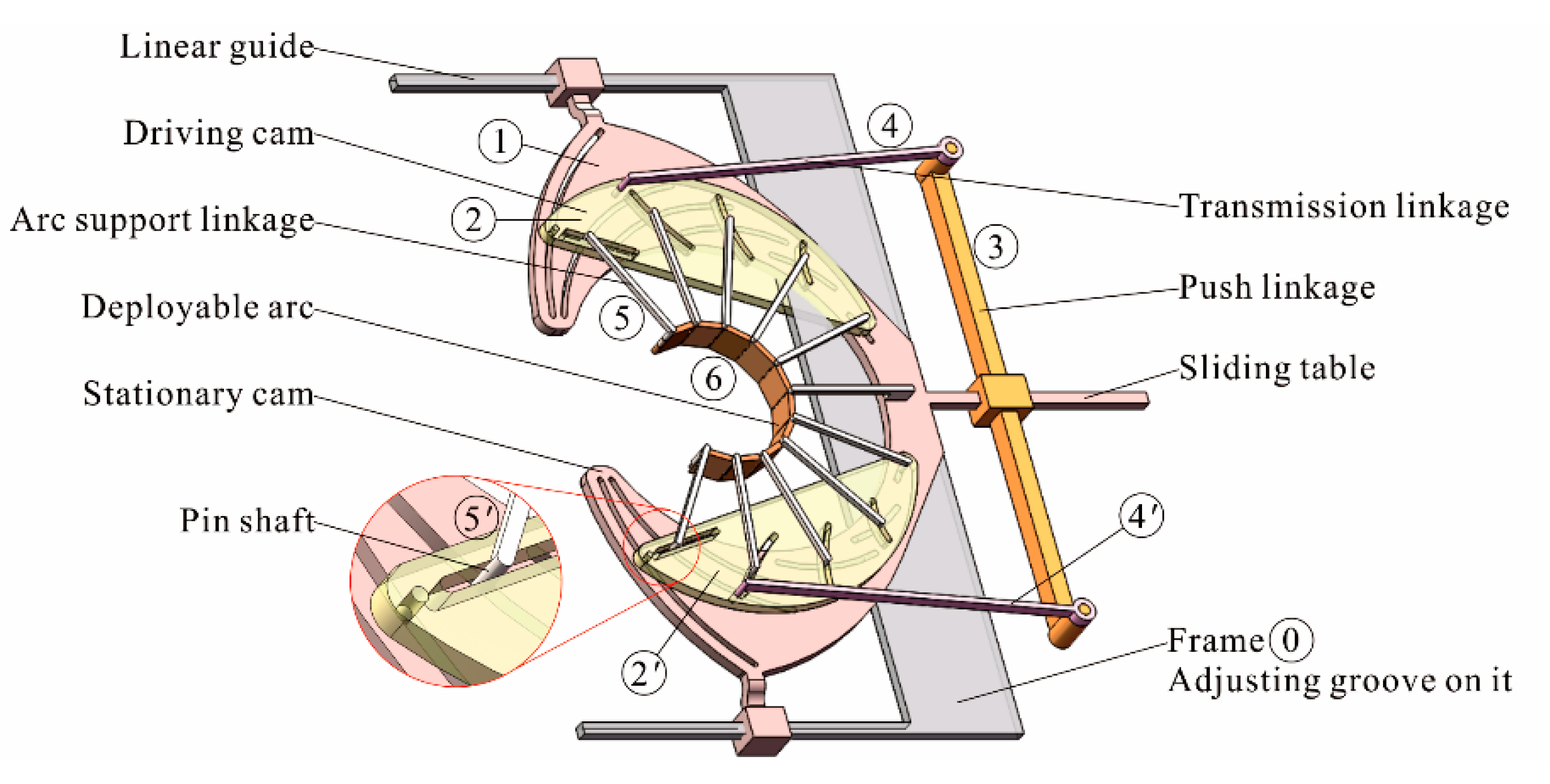
Symmetry Free Full Text Design And Experiment Of Symmetrical Shape Deployable Arc Profiling Mechanism Based On Composite Multi Cam Structure Html

Using Cad To Synthesize Mechanisms Part 2 Engineers Rule

Cam Joints 1 Determine The Mobility And The Numbe Chegg Com

Mechanisms
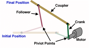
Design Cookbook Linkages
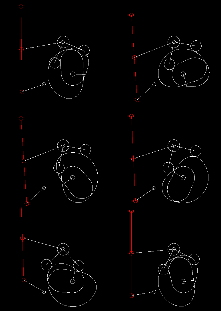
Q Tbn 3aand9gcqlktv Np96oszt1i7galyjrxjxaqxz5p5pqa Usqp Cau
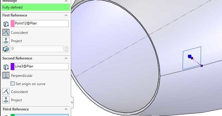
Using Cad To Synthesize Mechanisms Engineers Rule

Q Tbn 3aand9gcsihnyaf7itve5rljgx9e1xjdcqlwtv2s8o5g Usqp Cau
Cam Mechanism Article About Cam Mechanism By The Free Dictionary

Conceptual Design And Dimensional Synthesis Of Cam Linkage Mechanisms For Gait Rehabilitation Sciencedirect

Mechanism Part 1 4 Bar Linkage Modeling Simulation Video Tutorial Solidworks Youtube
Q Tbn 3aand9gctqzui4vxtnhejedmf6 Xmvh8xoq2flh73ubw Usqp Cau
Mechanisms Levers And Linkages Ppt Download

Linkage Mechanical Wikipedia
Mechanism Engineering Wikipedia

Solved Mechanisms And Machine Theory 7 Score 16 In Chegg Com
Examples Of Mechanisms
Q Tbn 3aand9gcqrrllcm6rl1vmmrrso61h9jrvwq0cynwogyxe1ii6gpvpeesf Usqp Cau

Q Tbn 3aand9gcqflox0v84g7ycw7or 04ylmt8h8siesihwua Usqp Cau

Q Tbn 3aand9gctaspc Djreznhq0j1zguxlterguy2gbmhupa Usqp Cau
Equivalency Of Circular Cam And Linkage Mechanisms Mechamechanisms Com
Mechanisms Index Page

Improving The Design Of High Speed Mechanisms Through Multi Level Kinematic Synthesis Dynamic Optimization And Velocity Profiling Sciencedirect

Understanding Degrees Of Freedom Youtube
Mechanisms Index Page

Cam Feature In Linkage Program Dave S Blog
Examples Of Mechanisms

Four Bar Slider Mechanism 2 Dof From A Mechanical Point Of View The Download Scientific Diagram

Conceptual Design And Dimensional Synthesis Of Cam Linkage Mechanisms For Gait Rehabilitation Sciencedirect

Mechdesigner Mechanism Motion And Cam Design Software

Fixed Cam Mechanism 5 Youtube Mechanical Design Mechanical Projects Machine Design
Q Tbn 3aand9gcqqaq2z392fkvhp Xjhxobk0xvvzjb1yyccbsstctinx0tn Lmi Usqp Cau
Motion Design 101 Mechanical Cam Types And Operation Machine Design
Robotics Free Full Text A Note On Equivalent Linkages Of Direct Contact Mechanisms Html
Q Tbn 3aand9gcqly9ou5e2a7j9p38trsz6lc Dalqlu Dyghq Usqp Cau

Four Bar Linkage Optimization In Simscape File Exchange Matlab Central

Pdf Conceptual Design And Dimensional Synthesis Of Cam Linkage Mechanisms For Gait Rehabilitation
Chapter 6 Cams

Linkages Cams Gears Etc Dave S Blog

Robotic Mechanisms Cam Mechanisms Robotpark Academy

S13 Design And Analyse Basic Mechanical Systems Year 1 Design And Technology Audit
Linkage Mechanisms Ppt Download

Mechanism Design 6 Bar Dwell Mechanism Youtube

Pdf An Efficient Parking Solution A Cam Linkage Double Parallelogram Mechanism Based 1 Degrees Of Freedom Stack Parking System

Q Tbn 3aand9gctcboavtdmarjy1564o1p3tqjyah 9isugegw Usqp Cau
Web Wpi Edu Pubs E Project Available E Project Unrestricted Cstm Final Report Pdf

The General Kinematic Pair Of A Cam Mechanism Intechopen
Q Tbn 3aand9gctbs4wqmibrxy0u2ydp95kcby7b6ng6akdfxg Usqp Cau

Cam Feature In Linkage Program Dave S Blog

Cam Feature In Linkage Program Dave S Blog
Q Tbn 3aand9gcq8epfsivlbv3uirrgdjh4mglxt5bqlsw0f3a Usqp Cau

A And C Rack And Pinion Four Bar Linkage And B Its Equivalent Download Scientific Diagram

Pdf Conceptual Design And Dimensional Synthesis Of Cam Linkage Mechanisms For Gait Rehabilitation
Robotics Free Full Text A Note On Equivalent Linkages Of Direct Contact Mechanisms Html
Examples Of Mechanisms

Chebyshev Straight Line Linkage Mechanism Youtube Metal Bending Lever Homemade Tools
Robotics Free Full Text A Note On Equivalent Linkages Of Direct Contact Mechanisms Html

Mechanism Design Crank Slider 4 Mechanism Linkage Inversions Youtube

Q Tbn 3aand9gcsw6kx1f36u8pw7i59qcnumx4mfsfy7vrio9w Usqp Cau

Notice Of Retractionsynthesis Of Coupler Curves With Combined Planar Cam Follower Mechanisms By Genetic Algorithm Semantic Scholar
Examples Of Mechanisms
Chapter 5 Planar Linkages

Mechanism Collection Of Tu Delft

Mechdesigner Mechanism Motion And Cam Design Software

Q Tbn 3aand9gctz5ckxaesxatdl lm7x5ricly Ixpo5u9w Usqp Cau
Q Tbn 3aand9gcrfgeaxal2qvg4vx8k8xucntxnwkihmng7nbq Usqp Cau

Equivalency Of Circular Cam And Linkage Mechanisms 2 Youtube

Q Tbn 3aand9gctvughnrn7ah6ddmn Rhzd8zz8kmt4ppxxi2w Usqp Cau
Q Tbn 3aand9gctaby2cgaqfhzx7wb6emkc5qdsj Z307irc6uhqkmflil3y2ugd Usqp Cau
Mechanical Engineering Dept Ppt Video Online Download
Examples Of Mechanisms

Solved Mechanisms And Machine Theory 7 Score 16 I Chegg Com

Q Tbn 3aand9gcsuq Ktjnlyx7de8z39agdrcf A Us9uy5pwq Usqp Cau

Cam Linkage Mechanism Synthesized By Mundo Et Al 06 To Generate Download Scientific Diagram

Schematic Representation Of A Generic Disc Cam Mechanism With Offset Download Scientific Diagram
Q Tbn 3aand9gcr07qs8ihhos5wdpb2rm36v3vnt 0yrm39s0q Usqp Cau
Solved Q1 What Are Two Advantages Of Cam Followers Over Chegg Com
Robotics Free Full Text A Note On Equivalent Linkages Of Direct Contact Mechanisms Html

Mechanical Gripper Mechanisms Robotics Bible Projects News Videos Books Events And More Robotics Bible Projects News Videos Books Events And More
Example Mechanisms Sheet
Hawthorne Project Title

Pdf High Speed Cam Design For Quick Action Linkage System

Pdf Conceptual Design And Dimensional Synthesis Of Cam Linkage Mechanisms For Gait Rehabilitation
Linkage Mechanisms Ppt Download

Optimal Design Of Toggle Linkage Mechanism For Clamping Applications Sciencedirect
Web Wpi Edu Pubs E Project Available E Project Unrestricted Cstm Final Report Pdf

Pin On Automata All Things

Mechanisms Index Page


